Monday 30 January 2017

TERTIARY WINDING OF TRANSFORMER - THREE PHASE TRANSFORMER

Electrical Transformer is a static device which transform electrical energy from one electrical circuit to another electrical circuit without any direct connection. It is also used for electrical power transmission (Step-Up) and distribution the electrical power (Step-Down) and Special purposes. Commonly we know that there are two windings in transformer, The primary winding and the secondary winding. The primary winding is used for input (not fixed) and the secondary winding is used for the output whether it depend upon the situation and requirement. Now there is a question asked an engineer from our Facebook group (Facebook-Group) that what is Tertiary winding in the three phase transformer, the advantages and disadvantages of tertiary winding.

Working Principle Of Transformer

The working principle of transformer is totally depends upon the Faraday's Law of mutual induction.
Faraday's Law of Mutual Induction is:
"Rate of change of flux linkage with respect to time is directly proportional to the induced EMF in a conductor or a coil."
As you all know well about the transformer working, I will try not to discuss here again. but the main constructional parts of the transformer I share below.

Main Constructional Parts of Transformer

There are following main part of transformer in construction.

  • Primary Winding
  • Secondary Winding
  • Magnetic Core of transformer
Now What is Primary winding? The Primary winding of transformer which produce magnetic flux when it is connected to electrical source. And What is the secondary winding? The Secondary winding of transformer is the flux, produce by primary winding, passes through the core will link with the secondary winding. This is also wound on the core of transformer and gives the desired output of the transformer. And the magnetic core of transformer is the magnetic flux produced by the primary winding that will pass through with low reluctance path linked with secondary winding and create a close magnetic circuit in the transformer.


tertiary winding how electrical blog


Tertiary Winding of Three Phase Transformer

As we already discuss, there are two windings in the transformer. There is another additional winding we used named "Tertiary Winding". This winding is used in the high rating transformer for the purposes below mentioned.  Because of this third winding, the transformer with tertiary winding is also known as three winding transformer.
Advantages of Tertiary Winding in three phase transformer
There are following advantages of tertiary phase winding.


  1. Tertiary Winding reduces the unbalancing in the primary due to unbalancing in three phase load.
  2. Tertiary Winding redistributes the flow of fault current.
  3. Sometime Tertiary Winding is required to supply an auxiliary load in different voltage level in addition to its main secondary load. This secondary load can be taken from tertiary winding of three winding transformer.
  4. As the tertiary winding is connected in delta formation in 3 winding transformer, it assists in limitation of fault current in the event of a short circuit from line to neutral.

Rating of Tertiary Winding.


Rating of tertiary winding depends upon its use. If it has to supply additional load, its winding cross - section and design philosophy is decided as per load, and three phase dead short circuit on its terminal with power flow from both sides of HV & MV. In case it is to be provided for stabilizing purpose only, its cross - section and design has to be decided from thermal and mechanical consideration for the short duration fault currents during various fault conditions single line to ground fault being the most onerous.

Saturday 28 January 2017

WHAT IS TRANSDUCER, ITS TYPES AND WHAT IS THE APPLICATIONS OF TRANSDUCER

transducer


What Transducer Is?

A transducer is an electronic device that converts energy from one form to another. Common examples include microphones, loudspeakers, thermometers, position and pressure sensors, and antenna. Although not generally thought of as transducers, photocells, LEDs (light-emitting diodes), and even common light bulbs are transducers. A transducer plays a very important role in any instrumentation system.

Types Of Transducer:

There are many types of the transducer. Transducer can be classified into main types as below,
  • Quantity to be measured
  • Principle of Operation

Transducer as Quantity to be measured

  • Temperature transducer
  • Pressure transducer
  • Displacement transducer
  • Flow transducer

Transducer as Principle of Operations

  • Chemical transducer
  • Photovoltaic transducer
  • Photoconductor transducer
  • Half effect transducer
  • Piezoelectric transducer

Ideal Characteristics of Transducer

  • High dynamic range
  • High repeatability
  • Low Noise
  • Low hysteresis

Friday 27 January 2017

RHOESTAT AND POTENTIOMETER - THE DIFFERENCE BETWEEN RHEOSTAT AND POTENTIOMETER

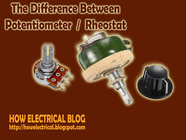
potentiometer and rheostat


As looking wise, The potentiometer and the rheostat are looking same but there is some difference between both. I have shared some knowledgeable summarised difference below for understanding. If you found any more difference, You can share with us on below comment box.

POTENTIOMETER

A potentiometer is a three terminal variable resistor, Usually, electricians used the potentiometer to adjust voltage, The Potentiometer can work as Rheostat but The Rheostat can not works as Potentiometer because of their properties. The Potentiometer controls the circuit's Signal level (not the power level).

RHEOSTAT

A Rheostat is two terminal variable resistor, Usually, electricians use the rheostat to adjust current.  The Rheostat can not work as Potentiometer (but vice versa). Electricians employ a Rheostat for handling the much higher voltage and current. A Rheostat is simply a variable resistor used to control the power to a load.

A Rheostat is used to vary the amount of current in the circuit but a potentiometer is used to vary the voltage between the second terminal and one of the outside terminal.

Wednesday 25 January 2017

UNDERSTAND THE HAZARDS OF ELECTRIC SHOCK ON BODY AND RULES FOR SAFE PRACTICE TO AVOID ELECTRIC SHOCK

Performance objectives

Understand the hazards of electric shock on human body and rules for safe practice to avoid electric shock. See how an amount of current is changed within the human body with the variation of resistance.

EQUIPMENT:                        

  • DC Ammeter
  • Multimeter with resistance  Range 9-12 Battery

What is Electric Shock

An electric shock occurs when a person comes into contact with an electrical energy source. Electrical energy flows through a portion of the body causing a shock. When Voltage increases current also increases. In most cases voltage up to 50 Volts is safe. Chart of Different Physiological effects of electricity

Safety Rules

The apparent reasons for accidents are
  1. Ignorance
  2. Fatigue
  3. Mental Pressure
  4. Faulty or Improper Tools 
  5. Wrong procedure and carelessness
  6. Rules for safe practice to avoid electric shock
  7. Be sure of conditions of the equipment's and dangers present before working on pieces of equipment. 
  8. Never Rely on safety devices.
  9. Never Remove the ground wire of three wire-input plugs.
  10. Do not work on cultured bench
  11. Do not work on wet floors
  12. Do not work alone
  13. Work with one hand behind you or in your pocket
  14. Never talk to anyone while working

MCB, MCCB, ACB AND VCB DIFFERENCE AND CHARACTERISTICS - CIRCUIT BREAKERS

Circuit Breakers of differents poles.


MCB (Miniature circuit breaker)

  • The characteristics of miniature circuit breaker are below,
  • MCB rated current is not more than 100 A. means the current limit (or current rating) is maximum 100A).
  • Trip characteristics are normally meant not adjustable.
  •  MCB operation is thermal based or thermal-magnetic.

MCCB (Moulded case circuit breaker)

  • The characteristics of Moulded case circuit breaker are below,
  • The current rating of MCCB is from 101 A to 1000 A.
  •  The Current of a trip (switch off the circuit) may be adjustable, means current rating we can adjust in MCCB.
  • MCCB operates in thermal or thermal-magnetic operation.

ACB (AIR Circuit Breaker)

  • The characteristics of ACB (Air Circuit Breaker) are below.
  • The current rating of ACB (Air circuit breaker) is from 1001 A to 10000 A.
  • Trip characteristics of Air Circuit Breaker (ACB) often fully adjustable including configurable trip thresholds and delays.
  • ACB (Air Circuit Breaker) often used in Main Electrical Panels (usually in medium voltage MV or high voltage electrical panels HV). ACB (Air circuit breaker) also usually used for main power distribution in a large industrial plant, where the breakers are arranged in drawn-out enclosures for ease of maintenance.

VCB (Vacuum Circuit Breaker)

  • Some important characteristics of Vacuum circuit breaker are below,
  • The VCB (Vacuum circuit breaker) current rating is up to 3000 Amperes.
  • The main characteristics of vacuum circuit breaker are, it interrupts the arc in a vacuum bottle.
  • These can be applied at up to 35 thousand volts.
Is there any other you know, Share with us from below comment box.

Monday 23 January 2017

WHAT IS DIELECTRIC - ELECTRICAL TECHNOLOGY BLOG - HOW ELECTRICAL WORKS.

A dielectric is an electrical insulator that can be polarized by an applied electric field.
When a dielectric is placed in an electric field, electric charges do not flow through the material as they do in a conductor, but only slightly shift from their average equilibrium positions causing dielectric polarization.

 Because of dielectric polarization, positive charges are displaced toward the field and negative charges shift in the opposite direction. This creates an internal electric field which reduces the overall field within the dielectric itself.

While the term "insulator" implies low electrical conduction, "dielectric" is typically used to describe materials with a high polarizability. The latter is expressed by a number called the dielectric constant.

The term insulator is generally used to indicate electrical obstruction while the term dielectric is used to indicate the energy storing capacity of the material (by means of polarization).
If the space between the plates of a capacitor is filled with an Dielectric, the capacitance of the capacitor will change compared to the situation in which there is vacuum between the plates.

The change in the capacitance is caused by a change in the electric field between the plates. The electric field between the capacitor plates will induce dipole moments in the material between the plates. These induced dipole moments will reduce the electric field in the region between the plates. A material in which the induced dipole moment is linearly proportional to the applied electric field is called a linear dielectric.

For linear dielectric:

Where K is called the dielectric constant. Since the final electric field E can never exceed the free electric field Efree, the dielectric constant k must be larger than 1.
The potential difference across a capacitor is proportional to the electric field between the plates.

Since the presence of a dielectric reduces the strength of the electric field, it will also reduce the potential difference between the capacitor plates (if the total charge on the plates is kept constant):

The capacitance C of a system with a dielectric is inversely proportional to the potential difference between the plates, and is related to the capacitance Cfree of a capacitor with no dielectric in the following manner.


Since k is larger than 1, the capacitance of a capacitor can be significantly increased by filling the space between the capacitor plates with a dielectric with a large k.
The electric field between the two capacitor plates is the vector sum of the fields generated by the charges on the capacitor and the field generated by the surface charges on the surface of the dielectric.

INDUSTRIAL WIRING COURSE - ELECTRICAL WIRING - LEARN ELECTRICAL DRAWING

how electrical drawing


Electrical Wiring or Industrial Wiring course files in which you can learn these following topics in the field of Electrical Engineering.

TOPICS YOU WILL LEARN

  1. Safety of Industry/industrial wiring safety/industry safety
  2. Drawings and symbols of electrical wiring.
  3. Wire types and preparations (include insulation materials, conductors, wire specification, coxial and multiway cables and insulation  removal process.)
  4. Soldering and termination (how to solder a wire connections, forming the wire, crimped joints, screw clamp terminals and termination coaxial cable.)
  5. Cable forming connections and routing (general intro about connections and routing, conductor and cable runs and conductors of different circuits.)
  6. Hardware (components mounting rails usually known as aluminuim rails, plastics trunking or usually known as cable channel made of plastic materisl, connector blocks and screw terminals).
  7. Active components like connectors and relays, contactors and transformers etc.
  8. Passive components like fuses, resistors and capacitors.
  9. Switched and lamps.
  10. Earthings and screenings (earthing the protective bonding circuit, screen connections and more)
  11. The most important and advaced thing is PLC Wiring. (In which you will learn about
  12. PLC installation, Power supply wiring, earthing and wiring of inputs and outputs.
Want to learn these all? Download these files with complete Wiring course from below link.


APPLIED ELECTRICAL TECHNOLOGY COURSE - ELECTRICAL BASIC

Electrical engineering course applied electrical technology for beginners and for professionals also to make strong your basic in the electrical field and it is also a big chance for all electrical engineers and relevant field to make basic strong in this field. So don't forget to download the complete course from the link I have shared below. Follow this blog by email from the below.

APPLIED ELECTRICAL TECHNOLOGY COURSE


EFFECTS OF ELECTRIC CURRENT - HOW ELECTRICAL WORKS

Current:

The rate of flow of charges from a specific point is known as electric current. There are many effects of electric current and we can categorise it as below,

Heating Effects

When electric charges move through a wire, they lose some of the energy to the atoms in the wire. On receiving the energy, The atoms vibrate more and more causing the wire to heat up. Some of the Electric Energy is changed to heat energy. The higher the resistance the more the heat energy.


The amount of heat generated is governed by Joule's first law:

Q = I2·R·t

In industry soldering, welding, cutting, drilling and working of electric furnaces are based on heating of electric current.

Chemical Effects

The passage of an electric current through a conducting liquid causes chemical reactions.
The resulting effects are called chemical effects of electric current.
Two major effects are:
  1. Electrolysis
  2. Electroplating

1-Electrolysis
In chemistry and manufacturing, electrolysis is a method of using a direct electric current (DC) to drive a chemical reaction.
Electrolysis is commercially highly important as a stage in the separation of elements from naturally occurring sources such as ores using an electrolytic cell.

2 Electroplating
The most common application of the chemical effect of electric current is electroplating.
In this process, there exists a liquid, usually called the electrolyte, through which current passes. Two electrodes, connected to the terminals of a battery with a switch in between, are inserted in the liquid.
Electroplating is done in industries to have an anti-reactive coating on the parts of machines so that they do not react with the raw material, to have an anti-corrosive coating for the machines so that they do not get corroded, and a heat-resistive coating for parts like boilers to resist the heat produced by the machinery. Gold plating is one of the most common applications of electroplating in ornament-making.

Magnetic Effects

If a magnetic compass is placed near a conductor carrying current (wire), the needle is deflected. This shows that a conductor carrying current has a magnetic field around it.
The magnetic field around a current carrying straight conductor is in concentric circles. It can be observed by passing a current carrying straight conductor through a cardboard and sprinkling iron filings on it. All motors, transformers, Alternators and most of the measuring electrical instruments use magnetic effect of electric current.

Electro-Plating Effect Example
Electro-Plating Effect Example.

TIME CONSTANT FOR R-L CIRCUIT - THEORY PLUS QUESTIONS

Consider the Resistance-Inductance circuit shown few lines below, In the circuit on previous slide, if the coil was not present, the current through the resistor (may be a lamp) would immediately rise to its maximum value of E/R when you closed the switch. With the coil in the circuit, as soon as current starts to flow, the self-induction in the coil produces an emf across the coil, which, by Lenz’s Law opposes the change in current through circuit, thus, the rise of current in the circuit is not as fast as that was in pure resistive circuit containing no inductive element (coil).

The lamp thus experiences the sum of two opposing emfs, a constant one from the power supply, and an opposite, time-dependent one equal to -L di/dt from the self induction of the coil.
Over time, the current increases more slowly as it settles down to final steady state value, which causes the emf from self-induction in the coil to decrease, and finally after some time the current in the circuit approaches to E/R.


To find an expression for the current in the circuit, we note that the sum of the voltages across the resistor and the inductor equal the voltage applied by the power supply, or:
rl ckt
The solution to this differential equation is:
which we can also write as:
where τL, the inductive time constant, equals L/R.

L/R Time Constant

The time constant of a series RL circuit equal to the value of inductance divided by the resistance:

T = L / R

where,
T = time constant in seconds
L = inductance in henries
R = resistance in ohms

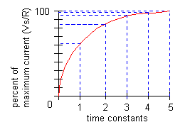
The LR TIME CONSTANT is a valuable tool for determining the time required for current in an inductor to reach a specific value. As shown in the illustration on next slide, one L/R time constant is the time required for the current in an inductor to increase to 63.2 percent of the maximum current. Inductor current build-up is considered complete at the end of 5 time constants. 
rl circiut

RL Decay Curve

Inductor current does not drop off at a steady rate. Rather, the rate of current decay is discharge is rapid at first, but slows considerably as the charge approaches zero.
During each time constant, the current decays 63.2% of the remaining distance to the minimum current level.
Inductor current decay is considered complete at the end of 5 time constants.
Questions for practice.

Q.1- What is the time constant of a series RL circuit where R = 1 kW and L = 1 mH?


Q.2- The steady-state maximum current through a 1.2 H inductor is 12 A. When this inductor is switched from the power source to a 1 W resistor, what is the current at the end of 3 time constants?

NUCLEAR POWER PROCESS - NUCLEAR FISSION PROCESS - RADIOACTIVE DECAY

Radioactive decay, also known as nuclear decay or radioactivity, is the process by which a nucleus of an unstable atom loses energy in the form of radiations. A material that spontaneously emits this kind of radiation - which includes the emission of energetic alpha particles, beta particles, and gamma rays - is considered radioactive. When unstable nuclei decompose in nature, the process is referred to as natural radioactivity or spontaneous radioactivity. When the unstable nuclei are prepared in the laboratory, the decomposition is called induced radioactivity.

Fission is a splitting of something into two parts.

In nuclear physics and nuclear chemistry, nuclear fission is either a nuclear reaction or a radioactive decay process in which the nucleus of an atom splits into smaller parts (lighter nuclei).
The fission process often produces free neutrons and photons (in the form of gamma rays), and releasing a very large amount of energy. When a nucleus fissions, it splits into several smaller fragments. These fragments, or fission products, are about equal to half the original mass. Two or three neutrons are also emitted. The sum of the masses of these fragments is less than the original mass. This 'missing' mass has been converted into energy according to Einstein's equation:

                                                E = mc2

Fission can occur when a nucleus of a heavy atom captures a neutron, or it can happen spontaneously.

The Fission Process

A neutron travels at high speed towards a uranium-235 nucleus. A neutron travels towards a uranium-235 nucleus. The neutron strikes the nucleus which then captures the neutron. The nucleus changes from being uranium-235 to uranium-236 as it has captured a neutron. The uranium-236 nucleus formed is very unstable. It transforms into an elongated shape for a short time.
The uranium-236 nucleus formed is very unstable. It transforms into an elongated shape for a short time. The uranium-236 nucleus formed is very unstable. It transforms into an elongated shape for a short time. It then splits into 2 fission fragments and releases neutrons. It then splits into 2 fission fragments and releases neutrons.

Nuclear Chain Reactions:

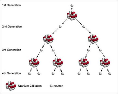
A chain reaction refers to a process in which neutrons released in fission produce an additional fission in at least one further nucleus. This nucleus, in turn, produces neutrons, and the process repeats. The process may be controlled (nuclear power) or uncontrolled (nuclear weapons). 
nuclear fission process
Image from University of Florida

U235 + n → fission + 2 or 3 n + 200 MeV

If each neutron releases two more neutrons, then the number of fissions doubles each generation. In that case, in 10 generations there are 1,024 fissions and in 80 generations about 6 x 10 23 fissions.

1 MeV (mega electron volts) = 1.609 x 10 -13 joules


Uranium-235 combines with a neutron to form an unstable Uranium-236, which quickly splits into barium-144 and krypton-89 plus three neutrons in the process of nuclear fission.
fission
Image from University of Dehli

fission process

Energy from Fission

Both the fission fragments and neutrons travel at high speed.  The kinetic energy of the products of fission are far greater than that of the bombarding neutron and target atom.

EK before fission << EK after fission

Energy is being released as a result of the fission reaction. The energy released can be calculated using the equation:

                                    E = mc2

Where:
E = energy released (J)
m = mass difference (kg)
c = speed of light in a vacuum (3 x 10⁸ ms-1)

The energy released from this fission reaction does not seem a lot. This is because it is produced from the fission of a single nucleus. Large amounts of energy are released when a large number of nuclei undergo fission reactions. Each uranium-235 atom has a mass of 3.9014 x 10⁻²⁵ kg.
The total number of atoms in 1 kg of uranium-235 can be found as follows: No. of atoms in 1 kg of uranium-235 = 1/3.9014 x 10-25.  No. of atoms in 1 kg of uranium-235 = 2.56 x 1024 atoms
If one uranium-235 atom undergoes a fission reaction and releases 2.385 x 10⁻¹¹ J of energy, then the amount of energy released by 1 kg of uranium-235 can be calculated as follows:
total energy = energy per fission x number of atoms
total energy = 2.385 x 10-11 x 2.56 x 1024
total energy = 6.1056 x 10¹³ J

Critical mass:

Although two to three neutrons are produced for every fission, not all of these neutrons are available for continuing the fission reaction. If the conditions are such that the neutrons are lost at a faster rate than they are formed by fission, the chain reaction will not be self-sustaining.
At the point where the chain reaction can become self-sustaining, this is referred to as critical mass.
In an atomic bomb, a mass of fissile material greater than the critical mass must be assembled instantaneously and held together for about a millionth of a second to permit the chain reaction to propagate before the bomb explodes. To maintain a sustained controlled nuclear reaction, for every 2 or 3 neutrons released, only one must be allowed to strike another uranium nucleus.
If this ratio is less than one then the reaction will die out; if it is greater than one it will grow uncontrolled (an atomic explosion). A neutron absorbing element must be present to control the amount of free neutrons in the reaction space.
Most reactors are controlled by means of control rods that are made of a strongly neutron-absorbent material such as boron or cadmium.

The nuclear force (or nucleon–nucleon interaction or residual strong force) is the force between two or more nucleons. It is responsible for binding of protons and neutrons into atomic nuclei. The energy released by such binding causes the masses of nuclei to be less than the total mass of the protons and neutrons which form them; this is the energy used in nuclear power and nuclear weapons. The force is powerfully attractive between nucleons at distances of about 1 femtometer (fm) between their centers, but rapidly decreases to insignificance at distances beyond about 2.5 fm. At very short distances less than 0.7 fm, it becomes repulsive, and is responsible for the physical size of nuclei, since the nucleons can come no closer than the force allows. So, if you feel anything important missed from here so you can comment below and mention How Electrical.

Sunday 22 January 2017

ELECTRICAL CIRCUIT COMPLETE TRAINING COURSE

We launched "Electrical Engineering Training Course"  in sub-branch of electrical engineering to learn about How electrical works and what is the latest technology in Electrical field and what's going on? So, the course name is "Electrical Circuit" in this course you can learn about these following topics,
technical courses free


  • DC Circuits
  • Ohm's law
  • Kirchhoff's laws
  • voltage
  • current
  • voltage and current division
  • nodal and mesh analysis
  • network theorems
  • AC circuits analysis
  • phasor concepts
  • AC power
  • Three phase AC circuits
  • Introduction to electronics and digital logics

You should have a background of the following topics:
  1. Coulomb's Laws
  2. Magnetic and electric fields.
  3. Dielectrics and capacitice.
  4. Resistance and electric curcuits.
  5. Electromagnetic induction.

Upon successful completion of this course, the student should be able to:

1. Understand the definitions of basic electrical quantities, Ohm's and Kirchhoff’s laws, and differences between practical/ideal sources.
2. Analyse simple series and parallel resitive circuits and simplify series/parallel connected sources and resistors.
3. Implement general nodal and mesh analysis and other circuit analysis techniques and select between them to achieve optimal solution.
4. Understand the concept of the sinusoidal forcing function and anlayse R/L/C cirucits in the frequency domain and convert the solution to the time domain.
5. Three phase circuits, and power calculations.
6. Basic electronics, and Basic Operational Amplifier circuits and systems.
7. Basic Digital Logic gates and Systems. Introduction to Programmable Logic Controllers (PLC)

Course Topics:


Units, charge, current, voltage, and power. Independent and Dependent voltage and current sources. Ohm's law.
Branches, nodes, paths, loops, and meshes. Kirchhoff's current and voltage laws. Single node and loop circuits. Reduction of series or parallel circuits. Voltage and current division.
Nodal voltage analysis and super-node. Mesh current analysis and super-mesh. Nodal vs. mesh analysis. Computer aided circuit analysis.
Linearity and superposition. Thevinin's and Nortons theorems, Source transformations, max. Power transfer, delta () – wye (Y) conversion. Selecting an optimal technique for solution.
The capacitor and inductor. Inductance and capacitance combinations.
Characteristics of sinusoids. The phasor and relationships of single phase for R, L, and C elements. Impedance and admittance. Circuit analysis techniques. R, L& C series and parallel resonance circuits. Phasor diagrams. Three-phase circuits, Wye (Y) and Delta () balanced sources and loads.
Power calculations for single and three phase circuits; power factor, power triangle. Power factor (improvement) correction.
Basic electronics including; p-n junction, diodes, transistors, simple transistor amplifier circuits, basic Operational Amplifiers (OPAMP), and applications.
Basic digital logic systems including: Numbering systems, Boolean’s algebra, Basic logic gates, basic digital circuits and systems. Introduction to Programmable Logic Controllers (PLC).

DOWNLOAD THIS COURSE FREE


To Download this course, without any charges click here or manually go to our online free electrical courses platform where We share electrical courses for your needs and knowledge.
Free electrical engineering courses download from www.freeelectrical.weebly.com

WHY WE USE AC MOTOR INSTEAD OF DC MOTOR - APPLICATIONS OF AC MOTORS AND APPLICATIONS OF DC MOTORS

Electric Motor


For electrical technology, Motor is known as the main unit of electrical technology. because of motor use in all industries with all machines and usually all the places normally. the Electrical motor is the main sub-sub-branch of electrical engineering because it is not easy to learn all concepts about electrical motor technology. There are many types and kinds of electrical motors like,

  1. AC motors
  2. DC motors

and there are also differents kinds in AC motors and DC motors as synchronous motors, induction motors, explosion proof, low voltage and motor with permanent magnet etc.


Where We Use AC Motors:

The alternating current electric motor (AC motors) are ideal for most applications linear, for fans, pumps, compressors, mills, machine tools, boilers, robots, generators and in many other products categories.
As regarding the choice of the type of electric motor for a given application, this is influenced by different factors, starting from the costs of purchase and operation, the yield, the efficiency, the periodic maintenance.


Where We Use DC Motors:


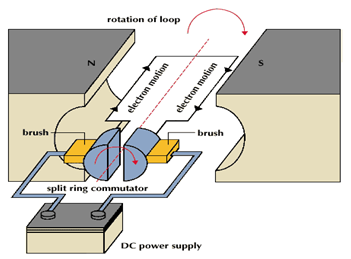
dc motorA DC motor is an electric motor that runs on direct current power. In any electric motor, the operation is dependent upon simple electromagnetism. A current carrying conductor generates a magnetic field, when this is then placed in an external magnetic field, it will encounter a force proportional to the current in the conductor and to the strength of the external magnetic field Resources and Information. is a device which converts electrical energy to mechanical energy. It works on the fact that a current carrying conductor placed in a magnetic field experiences a force which causes it to rotate with respect to its original position. Practical DC Motor consists of field windings to provide the magnetic flux and armature which acts as the conductor.

Applications of DC Motors

Series Motors

The series DC motors are used where high starting torque is required, and variations in speed are possible. For example – the series motors are used in Traction system, Cranes, air compressors.

Shunt Motors

The shunt motors are used where constant speed is required and starting conditions are not severe. The various applications of DC shunt motor are in Lathe Machines, Centrifugal Pumps, Fans, Blowers, Conveyors, Lifts, Weaving Machine, Spinning machines, etc.

Compound Motors


The compound motors are used where higher starting torque and fairly constant speed is required. The examples of usage of compound motors are in Presses, Shears, Conveyors, Elevators, Rolling Mills, Heavy Planners, etc.

Saturday 21 January 2017

ELECTRICAL POWER | ENERGY METER DISCUSSIONS

energy meter

Theory: - 

Energy meter is an instrument which measures electrical energy. It is also known as watt-hour (Wh) meter. It is an integrating device. There are several types of energy meters single phase induction type energy meter are very commonly used to measure electrical energy consumed in domestic and commercial installation. Electrical energy is measured in kilo watt-hours (kWh) by this energy meter. 

Construction: - 

A single phase induction type energy meter consists of driving system, moving system, braking system and registering system. Each of the systems is briefly explained below. 

Driving system: -

This system of the energy meter consists of two silicon steel laminated electromagnets. M1 & M2 as shown in fig.1The electromagnet M1 is called the series magnet and the electromagnet M2 is called the shunt magnet. The series magnet M1 carries a coil consisting of a few turns of thick wire. This coil is called the current coil (CC) and it is connected in series with the circuit. The load current flows through this coil. The shunt magnet M2 carries a coil consisting many turns of thin wire. This coil is called the voltage coil (VC) and is connected across the supply it consist of current proportional to the supply voltage. Short circuited copper bands are provided on the lower part of the central limb of the shunt magnet.

By adjusting the position of these loops the shunt magnet flux can be made to lag behind the supply voltage exactly 90° . These copper bands are called power factor compensator (PFC). A copper shading band is provided on each outer limb of the shunt magnet (fc1 &fc2) these band provides frictional compensation.

Moving system: -

The moving system consists of a thin aluminium disc mounted on a spindle and is placed in the air gap between the series and the shunt magnets. It cuts the flux of both the magnet forces are produced by the fluxes of each of the magnets with the eddy current induced in the disc by the flux of the other magnets. Both these forces act on the disc. These two forces constitute a deflecting torque.

Braking system: -

The braking system consists of a permanent magnet called brake magnet. It is placed near the edge of the disc as the disc rotates in the field of brake magnet eddy current are induced in it. These eddies current react with the flux and exert a torque. This torque acts in direction so that it opposes the motion of disc. The braking torque is proportional to the speed of the disc.

Registering system: -

The disc spindle is connected to a counting mechanism this mechanism records a number which is proportional to the number of revolutions of the disc the counter is calibrated to indicate the energy consumed directly in kilo watts-hour (kWh)

DC NETWORK THEOREM - ELECTRICAL ENGINEERING BASIC


Current: “Rate of flow of electric charge.”
time
Charge
I = Coulombs/Sec or Ampere
Note:-
1. Direction of current is same as the direction of motion of +Ve charge or opposite to the direction of
motion of –Ve charge.

Voltage:Energy required in transferring a charge of one coulomb from one point to
another point.”
Charge(Q)
Energy(W)
V = Joule/Coulomb or Volts

EMF (Electromotive force): “The EMF of a voltage source is the energy imparted by
the source to each coulomb of the charge passing through it.”
Charge(Q)
Energy(W)
E = Joule/Coulomb or Volts

Potential Difference: “The pd between two points is the energy required in transferring a
charge of coulomb from one point to another point.”
Charge(Q)
Energy(W)
pd = Joule/Coulomb or Volts

Voltage drop: “The voltage drop between two points is the decrease in energy required
in transferring a charge of coulomb from one point to another point.”
Charge(Q)
Energy(W)
Voltage drop = Joule/Coulomb or Volts

Resistance: “Electric resistance is the property of material which offers opposition to the
flow of current and dissipates energy.”
a
l
R = ñ Ohm or _ (Law of resistance)
Where l = Length of the wire
a = cross sectional area of the wire
ñ = Resistivity or Specific Resistance of the material
Note:-

1. Resistance also depends on temperature.

WHAT IS COHESIVE DEVICES? DISCUSSIONS


Coherence in writing means achieving a consistent relationship among parts. Cohesive devices show the logical relationships between the various parts of an essay as well as between sentences and paragraphs.
Cohesive devices include: transitional words and expressions,  paragraph hooks
cohesive devices are like bridges between parts of your paper
They are cues that help the reader to interpret ideas in the way that you, as a writer, want them to understand cohesive devices help you carry over a thought from one sentence to another, from one idea to another, or from one paragraph to another with words or phrases.
cohesive devices link your sentences and paragraphs together smoothly so that there are no abrupt jumps or breaks between ideas.

Cohesive words and phrases  are used to link sentences and paragraphs, to show which direction your thought patterns are going, to help the reader accurately follow your train of thought.
They signal the relationships among the various parts of your subject.

Types Of Cohesive Devices

There are several types of cohesive devices, and each category leads your reader to make certain connections or assumptions about the areas you are connecting.
Some lead your reader forward and imply the "building" of an idea or thought,
while others make your reader compare ideas or draw conclusions from the preceding thoughts.
Before, meanwhile, later, soon, at last, earlier, thereafter, afterward, by that time, from then on, first, next, now, presently, shortly, immediately, finally
Likewise, similarly, once again, once more
But, yet, however, although, whereas, though, even so, nonetheless, still, on the other hand, on the contrary As a result, consequently, therefore, hence, for this reason
I knew my dieting had gotten out of hand, but when I could actually see the movement of my heart beating beneath my clothes, I knew that I was in trouble. At first, the family doctor reassured my parents that my rapid weight loss was a “temporary phase among teenage girls.” However, when I, at fourteen years old and five feet tall, weighed in at 63 pounds, my doctor…
Transition words are audience cues that help the reader shift from one paragraph to the next.
These connections between paragraphs help the reader see the relationships of the various parts.
Transition words or phrases at the beginning of a new paragraph—such as first, second, next, another, finally, on the other hand, however—show the reader where the essay is going next.
In addition to transition words, writers often tie paragraphs together by repeating a key word or idea from a previous paragraph in the opening sentence of the next paragraph.
This “hooks” the paragraphs together, creating for the reader a logical flow of thought.


DC MACHINES AND COMPUTER AIDED DESIGN QUESTIONS FOR PRACTICES


  1. Determine diameter and length for 100 Kw, 230V, 750 rpm, 6 pole dc machine. How the choice is made for selecting pole numbers in a dc machine.

  1. Find the suitable number of poles and the dia. of the core of a 400Kw, 550 V, 180 rpm d.c. generator having 92% efficiency. Assume an average flux density in the air gap of about 0.6 wb/m2 and ampere conductor per meter to be 35000.

  1. Explain the use of a digital computer in designing of an electrical machine giving its advantages and limitations.

  1. Give Computer Aided Design approaches  by the following methods:

(a)    Analysis
(b)   Synthesis
(c)    Hybrid

  1. Give concept of optimization as applied to the design of electrical machines. Name some of the optimization techniques employed in design and briefly describe its general procedure.

  1. Explain the design procedure for design of stator of a 3-phase turbo-alternator and write a flow chart to estimate the main dimensions. What statements will have to be changed to make the same program valid for a water wheel generator.

  1. If the design data of a single phase transformer is known, write flow chart for determining % regulation and efficiency at different load currents and power factors.

  1. Give design procedure for design of rotor of a wound rotor induction motor.


  1. Explain, with flow chart, how the performance of a water wheel generator may be estimated from the design data and what steps can be taken to improve the performance.

  1. Write a flow chart to design a d.c. machine and estimate its efficiency.

  1. Write a procedure to obtain the leakage reactance of a 3-phase core-type transformer with concentric winding with its relevant computer flow chart and indicate how the value of leakage reactance be controlled by design parameters.

INDUCTION MOTOR QUESTIONS FOR PRACTICES

induction motors

1.      Drive the output equation of a 3-phase induction motor and also explain how the magnetic and electric loading is selected.

2.      Write down the steps to find out the main dimensions of a 3-phase IM. Also draw a flow chart for it.

3.      Explain and find out flux density in stator teeth.

4.      Explain how the rotor is designed of a 3-phase ship ring induction motor. Also draw a flow chart for it.
5.      Estimate the stator slot leakage reactance for 1-Layer winding.
6.      Write down step by step how the circle diagram is drawn for an induction motor?
7.      Calculate the main dimension, turns per phase, Number of conductors, slots, cross-section of the  conductor of a 50 KW, 415 volts, 3 phase,, 50 Hz, 1000 RPM, slip ring  induction motor. Given Bav = 0.52T, η= 0.9, pf =0.89 lagging, =32000 ac /m, δ= 5A /mm².

8.      A 20-kw, 3-phase, 6-pole, 50-Hz, 400 V delta connected cage rotor induction motor has 54 stator slots, each containing 10 conductors. Design suitable number of rotor slots and determine the value of bar and end ring currents. The machine has efficiency of 85% and power factor 0.85 lagging. Also find the bar and end ring sections, if current density is 6.0 A/mm². Assume rotor mmf as 85% of the stator mmf.

9.      Describe the significance of B30 in a  3-phase induction motors. A 75 kw, 3300V, 50 Hz, 8-pole, 3-ph, star connected induction motor has a magnetizing current which is 35% of full load current. Calculate the number of stator winding turns per phase if the mmf required for flux density at 600 from the inter polar axis is 500 A. Assume winding factor = 0.95, full load efficiency = 0.94 and full load power factor = 0.86.

10.  Estimate the main dimensions & air gap length for a 3-phase, 20 HP, 400 V, 6-pole, 50 Hz, 970 RPM induction motor suitable for a star-delta starting. Assume magnetic and electric specific loadings as 0.45 wb/m2 and 23000 ac/m respectively, ratio of core length to pole pitch 0.85, full load efficiency 0.88 and power factor 0.89.

11.  Estimate the main dimensions, number of radial ducts, number of stator slots, number of turns per phase, conductors per slot and slot dimensions for 7.5 kW, 415 V, 3-phase, delta-connected, 4-pole, 50 Hz squirrel-cage induction motor. The flux per pole is 0.015 Wb. Assume efficiency 85% and power factor as 0.85 lagging.


12.  Determine the main dimensions, turns per phase, number of slots, conductor section and slot area of 200 H.P, 3 phase, 50Hz, 400 Volts, 1480 r.p.m. slip ring induction motor. Assume Bav = 0.5 wb/m2, ac = 30,000 amp conductor / meter, efficiency = 0.9 and power factor = 0.9, current density = 3.5 amp per mm2.

13.  Design a 10 HP, 415 V, 3-phase, 50 Hz, 1440 rpm, squirrel cage induction motor. The machine is to be started by a star delta starter. Assume all suitable data yourself.