The frequency of a system is dependent on active power balance frequency is a common factor throughout the system, a change in active power demand at one point is reflected throughout the system by a change in frequency.
Because there are many generators supplying power into the system, some means must be provided to allocate change in demand to the generators. A speed governor on each generating unit provides the primary speed control function, while supplementary control. originating at a central control center allocates generation.
In an interconnected system with two or more independently controlled areas) in addition to control of frequency, the generation within each area has to be controlled so as to maintain scheduled power interchange. The control of generation and frequency is commonly referred to as load-frequency control (LFC). We will first review the requirements for primary speed governing and then discuss supplementary control.
REASONS FOR THE NEED OF MAINTAINING CONSTANT FREQUENCY
The speed of A.C motors are directly related to the frequency. If the normal operating frequency is 50 Hz and the turbines run at speeds corresponding to frequencies less than 47.5 Hz or above 52.5 Hz, then the blades of the turbines may get damaged.
The operation of a transformer below the rated frequency is not desirable. When frequency goes below rated frequency at constant system voltage then the flux in the core increases and then the transformer core goes into the saturation region.
With reduced frequency the blast by ID fans and FD fans decrease, and so the generation decreases and thus it becomes a multiplying effect and may result in shut down of the plant.
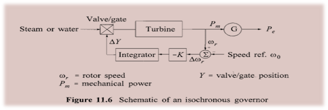
Isochronous governor
The adjective isochronous means constant speed. An isochronous governor adjusts the turbine valve/gate to bring the frequency back to the nominal or scheduled value.
The measured rotor speed ⱳr, is compared with reference speed ⱳo, The error signal (equal to speed deviation) is amplified and integrated to produce a control signal which actuates the main steam supply valves in the case of a steam turbine, or gates in the case of a hydraulic turbine.
Because of the reset action of this integral controller, Will reach a new steady state only when the speed error ⱳr is zero.
The increase in Pe causes the frequency to decay at a rate determined by the inertia of rotor. As the speed drops, the turbine mechanical power begins to increase.
This in turn causes a reduction in the rate of decrease of speed, and then an increase in speed when the turbine power is in excess of the load power.
The speed will ultimately return to its reference value and the steady-state turbine power increases by an amount equal to the additional load.
An isochronous governor works satisfactorily when a generator is supplying an isolated load or when only one generator in a multi-generator system is required to respond to changes in load.
Governor with speed-droop characteristic
The isochronous governors cannot be used when there are two or more units Connected to the same system since each generator would have to have precisely the Same, Speed setting.
Otherwise, they would fight each other, each trying to control System frequency to its own setting.
For stable load division between two or more units operating in parallel, the governors are provided with a characteristic so that the Speed drops as the load is increased.
Governor with speed-droop characteristic
The speed-droop or regulation characteristic may be obtained by adding a Steady-state feedback loop around the integrator
Percent speed regulation or droop
The value of R determines the steady-state speed versus load characteristic of the generating unit .
The ratio of speed deviation frequency deviation to change in valve/gate position or power output is equal to R, The parameter R is referred to as speed regulation or droop. It can be expressed in percent as
If two or more generators with drooping governor characteristics are connected to a power system, there will be a unique frequency at which they Will share a load Change.
Consider two units with droop characteristics as shown in Figure, they are initially at nominal frequency ƒo, with outputs P1 and P2.
When a load increase causes the units to slow down, the governors increase output until they reach a new common operating frequency ƒ'.
Time response
The time response of a generating unit, With a speed-droop governor, when subjected to an increase in load.
Because of the droop characteristic, the increase in power output is accompanied by a steady-state speed or frequency deviation.
Control of Generating Unit Power Output
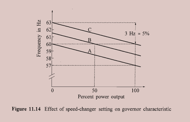
Relationship between speed and load can be adjusted by changing "load reference set point“.
Accomplished by operating speed-changer motor
Three characteristics representing three load reference settings shown, each with 5% droop.
At 60 Hz, characteristic A results in zero output;
characteristic B results in 50% output;
characteristic C results in 100% output
characteristic B results in 50% output;
characteristic C results in 100% output
Power output at a given speed can be adjusted to any desired value by controlling load reference
When two or more units are operating in parallel:
Adjustment of droop establishes proportion of load picked up when system has sudden changes.
Adjustment of load reference determines unit output at a given frequency


This comment has been removed by a blog administrator.
ReplyDeleteThis comment has been removed by a blog administrator.
ReplyDeleteYou have a real ability for writing unique content. I like how you think and the way you represent your views in this article. I agree with your way of thinking. Thank you for sharing. note frequencies
ReplyDeleteEveryone who visit this blog can easily understand after having detailed content here. Thanks for sharing this useful information with us via this blog.
ReplyDeleteParaflex
Wire & Cable Industry