Showing posts with label DC Motor. Show all posts

Sunday, 22 January 2017

WHY WE USE AC MOTOR INSTEAD OF DC MOTOR - APPLICATIONS OF AC MOTORS AND APPLICATIONS OF DC MOTORS

Electric Motor


For electrical technology, Motor is known as the main unit of electrical technology. because of motor use in all industries with all machines and usually all the places normally. the Electrical motor is the main sub-sub-branch of electrical engineering because it is not easy to learn all concepts about electrical motor technology. There are many types and kinds of electrical motors like,

  1. AC motors
  2. DC motors

and there are also differents kinds in AC motors and DC motors as synchronous motors, induction motors, explosion proof, low voltage and motor with permanent magnet etc.


Where We Use AC Motors:

The alternating current electric motor (AC motors) are ideal for most applications linear, for fans, pumps, compressors, mills, machine tools, boilers, robots, generators and in many other products categories.
As regarding the choice of the type of electric motor for a given application, this is influenced by different factors, starting from the costs of purchase and operation, the yield, the efficiency, the periodic maintenance.


Where We Use DC Motors:
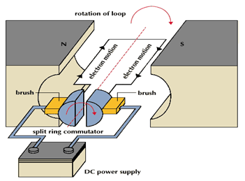


dc motorA DC motor is an electric motor that runs on direct current power. In any electric motor, the operation is dependent upon simple electromagnetism. A current carrying conductor generates a magnetic field, when this is then placed in an external magnetic field, it will encounter a force proportional to the current in the conductor and to the strength of the external magnetic field Resources and Information. is a device which converts electrical energy to mechanical energy. It works on the fact that a current carrying conductor placed in a magnetic field experiences a force which causes it to rotate with respect to its original position. Practical DC Motor consists of field windings to provide the magnetic flux and armature which acts as the conductor.

Applications of DC Motors

Series Motors

The series DC motors are used where high starting torque is required, and variations in speed are possible. For example – the series motors are used in Traction system, Cranes, air compressors.

Shunt Motors

The shunt motors are used where constant speed is required and starting conditions are not severe. The various applications of DC shunt motor are in Lathe Machines, Centrifugal Pumps, Fans, Blowers, Conveyors, Lifts, Weaving Machine, Spinning machines, etc.

Compound Motors


The compound motors are used where higher starting torque and fairly constant speed is required. The examples of usage of compound motors are in Presses, Shears, Conveyors, Elevators, Rolling Mills, Heavy Planners, etc.

Saturday, 21 January 2017

DC MACHINES AND COMPUTER AIDED DESIGN QUESTIONS FOR PRACTICES


  1. Determine diameter and length for 100 Kw, 230V, 750 rpm, 6 pole dc machine. How the choice is made for selecting pole numbers in a dc machine.

  1. Find the suitable number of poles and the dia. of the core of a 400Kw, 550 V, 180 rpm d.c. generator having 92% efficiency. Assume an average flux density in the air gap of about 0.6 wb/m2 and ampere conductor per meter to be 35000.

  1. Explain the use of a digital computer in designing of an electrical machine giving its advantages and limitations.

  1. Give Computer Aided Design approaches  by the following methods:

(a)    Analysis
(b)   Synthesis
(c)    Hybrid

  1. Give concept of optimization as applied to the design of electrical machines. Name some of the optimization techniques employed in design and briefly describe its general procedure.

  1. Explain the design procedure for design of stator of a 3-phase turbo-alternator and write a flow chart to estimate the main dimensions. What statements will have to be changed to make the same program valid for a water wheel generator.

  1. If the design data of a single phase transformer is known, write flow chart for determining % regulation and efficiency at different load currents and power factors.

  1. Give design procedure for design of rotor of a wound rotor induction motor.


  1. Explain, with flow chart, how the performance of a water wheel generator may be estimated from the design data and what steps can be taken to improve the performance.

  1. Write a flow chart to design a d.c. machine and estimate its efficiency.

  1. Write a procedure to obtain the leakage reactance of a 3-phase core-type transformer with concentric winding with its relevant computer flow chart and indicate how the value of leakage reactance be controlled by design parameters.

DC MACHINES AND SYNCHRONOUS MACHINES - QUESTIONS FOR PRACTICES

dc machines

  1. Explain construction and working principle of dc machines with the help of a neat diagram. Drive an emf equation for the same. What is back emf?
  2. What are the different efficiency associated with dc generator and dc motors explain?
  3. Drive an expression for torque in case of dc machine.
  4. A d.c. generator has an armature emf of 100 V when the useful flux per pole is 20 mWb, and the speed is 800 rpm. Calculate the generated emf (i) with the same flux and a speed of 1000 rpm, (ii) with a flux per pole of 24 mWb and a speed of 90 rpm. (Ans.:- (i) 125 V, (ii) 135 V)
  5. An 8 pole dc generator has 500 armature conductors and a useful flux of 0.05 Wb. What will be the emf generated, if it lap connected and runs at 1200 rpm? What must be the speed at which it is to be driven to produce the same emf, if it is wave wound? (Ans.:- 500V, 300 rpm)
  6. A 4 pole dc shunt generator with lap connected armature has field and armature resistance of 80 Ω and 0.1 Ω respectively. It supplies power to 50 lamps rated for 100 volts, 60 watts each. Calculate the total armature current and the generated emf by allowing a contact drop of 1 V per brush. (Ans.:- 26 A, 104.6 V)
  7.  A d.c. shunt machine connected to 230 V supply has resistance of armature as 0.115 Ω and of field winding as 115 Ω. Find the ratio of the speed as a generator to the speed as a motor with the line current in each case being 100 A. (Ans.:- 1.1052:1)
  8. A d.c. shunt motor draws 10 A at no load from 230 V mains and runs at 1500 rpm. At full load, armature current is 100 A and speed is 1470 rpm. Armature resistance of the motor is 0.1 Ω and field current negligible. Find (a) back emf at no – load and full load (b) speed at which armature should be run to make it deliver 100 A at 220 V as a generator. Assume same flux as with motor operation at full load of 10 A. (Ans.:- (a) 229 V , 220 V (b) 1536.8 rpm)
  9. A 200 V dc series motor runs at 500 rpm when taking a current of 25 A. The resistance of the armature is 0.5 Ω and that of the field is 0.3 Ω. If the current remains constant, calculate the resistance necessary to reduce the speed to 250 rpm. (Ans.:- 3.6 Ω)
  10. A d.c. series motor has an armature resistance of 0.12 Ω and field resistance of 0.08 Ω. The supply voltage across the motor terminals is 230 V. Determine the back emf and power developed by the motor when line current drawn by motor is 30 A. (Ans.:- 224 V, 6.72 kW)

  1. What are the different types of synchornous machines ? Explain the principle of operation of a 3-phase synchronus motor. Why it is not self starting.

  1. Why the field winding of synchronus generators is placed on rotor.

  1. Draw and explain V-curve for synchronous motor

Friday, 20 January 2017

SYNCHRONOUS MOTOR - CONSTRUCTION OF SYNCHRONOUS MOTOR

Synchronous Machine


Construction of Synchronous Machines:

Stator:
The stator is similar in construction that of a induction motor.
It is made up of laminated sheet steel having slot on its inner periphery.

Three phase winding is placed in the slot on stator and it serves as armature winding.

Rotor two types Salient:
  • for low speed Non-Salient (cylindrical rotor)
  • for high speed  Slip rings:


Two slip ring at rotor shaft to provide supply to field winding

Brushed: Two brushes Shaft:
Bearings:

Principle of operation:


Generator: Field produced on rotor by dc current through slip rings
Rotor field is turned at synchronous speed (Ns) by a prime mover.
EMFs induced in stator coils with frequency given by Motor:
The stator is wound for the similar number of poles as that of rotor, and fed with three phase AC supply. 

The 3 phase AC supply produces rotating magnetic field (RMF) in stator.
The rotor winding is fed with DC supply which magnetizes the rotor.
The rotor gets locked to the RMF and rotates unlike induction motor at synchronous speed under all load condition

Why Synchronous motor is not self starting?

How to make it self starting?

Consider a two pole synchronous machine as shown in figure below
Why Synchronous motor is not self starting?
Now, the stator poles are revolving with synchronous speed (lets say clockwise). If the rotor position is such that, N pole of the rotor is near the N pole of the stator (as shown in first schematic of above figure), then the poles of the stator and rotor will repel each other, and the torque produced will be anticlockwise.

The stator poles are rotating with synchronous speed, and they rotate around very fast and interchange their position. But at this very soon, rotor can not rotate with the same angle (due to inertia), and the next position will be likely the second schematic in above figure. In this case, poles of the stator will attract the poles of rotor, and the torque produced will be clockwise.
Hence, the rotor will undergo to a rapidly reversing torque, and the motor will not start.

How to make it self starting?


But, if the rotor is rotated upto the synchronous speed of the stator by means of an external force (in the direction of revolving field of the stator), and the rotor field is excited near the synchronous speed, the poles of stator will keep attracting the opposite poles of the rotor (as the rotor is also, now, rotating with it and the position of the poles will be similar throughout the cycle). Now, the rotor will undergo unidirectional torque. The opposite poles of the stator and rotor will get locked with each other, and the rotor will rotate at the synchronous speed.
Below is comment portion, not just for see, it is for your feedback and questions or suggestions about this topic. So kindly use this comment sections.

SINGLE PHASE INDUCTION MOTOR - CONSTRUCTION OF ELECTRIC MOTOR

Actual 1-phase induction motors are,
  1. Ceiling fans
  2. Other single phase induction motor: 


Construction

Construction is similar as that of 3-phase squirrel induction motor
A single phase induction motor has two main parts

Stator

Similar to 3-phase induction motor
consisting of a steel frame that supports a hollow, Laminated cylindrical core core, constructed from stacked laminations (why?), having a number of evenly spaced slots, providing the space for the stator winding.

Rotor

Squirrel cage rotor is used
aluminum bus bars shorted together at the ends by two aluminum rings.

Shaft:

Should withstand maximum breaking strength

Bearing:

Roller or ball bearing

It is used in vacuum cleaner, fans, washing machine, centrifugal pump, blowers, washing machine, small toys etc.

Principle:

When stator winding is fed from a single phase supply, an alternating (pulsating) field is produced.
Due to this alternating flux an alternating EMF (current) is induced in the rotor conductors
Now when a current carrying conductor is place in magnetic filed it experiences a force.
But after each half cycle the direction of induced current is change and hence the direction of force (torque) is changed after each half cycle. So pulsating flux acting on stationary squirrel cage rotor can’t produce rotation and therefore 1-phase induction motor is not self starting.
However, if the rotor o such machine is given initial start by hand or otherwise in either direction, then motor starts rotating in that direction. Above peculiar behavior can be explained by

Double filed revolving theory

To make it self-starting, it can be temporarily converted into a two-phase motor while starting. This can be achieved by introducing an additional 'starting winding' also called as auxillary winding.
Hence, stator of a single phase motor has two windings: (i) Main winding and (ii) Starting winding (auxiliary winding). These two windings are connected in parallel across a single phase supply and are spaced 90 electrical degrees apart. Phase difference of 90 degree can be achieved by connecting a capacitor in series with the starting winding.

Hence the motor behaves like a two-phase motor and the stator produces revolving magnetic field which causes rotor to run. Once motor gathers speed, say upto 80 or 90% of its normal speed, the starting winding gets disconnected form the circuit by means of a centrifugal switch, and the motor runs only on main winding.

Type of single phase induction motors

The  single phase induction motors are made self starting by providing an additional flux by some additional means( Additional winding ). Now depending upon these additional means the single phase induction motors  are classified as:
  • Resistance start induction motor
  • Capacitor start induction motor
  • Capacitor start capacitor run induction motor
  • Permanent capacitor motor
  • Shaded pole induction motor.

Friday, 13 January 2017

WHY POLE SHOE HAS BEEN GIVEN A SPECIFIC SHAPE

So as you know, pole shoe has been given a specific shape, So why it is need for a specific shapoe? I will share two main problems of this scenario.


  1. Pole shoe enlarges the area of armature core to come across the flux and which is necessory to produce larger induced EMF. So to acheive this, pole shoe has been given a particular shape.
  2. And (for given a shape) It is necessory that  maximum area of the armature comes across the magnetic field produced by the field windings.
pole shoe

WHAT ARE THE FUNCTION OF YOKE? DEFINE THE FUNCTION AND HOW TO CHOOSE THE MATERIAL FOR YOKE?

So first of all I would like to share some thing (basic) about Yoke, What is Yoke? How to choose material? OKay!!
Yoke is the body part of any motor whether it is dc motor or AC motor. Both have yoke, Yoke is the structure and body of motor.

The Functions of Yoke are:

  1. It provide mechanically support to the poles.
  2. It serves the purpose of outer most cover of the motor.
  3. It provide a path of low reluctance for flux.
  4. It forms a part of the magnetic circuits.
And in the last, It is prepared by Cost Iron, For large machines, we used rolled steel, silicon steel which provides high permeability.

motor yoke

HOW THE REVERSE DIRECTION OF ROTATION OF DC MOTOR.

To reverse the direction of rotation of DC motor, either it is main field's produced by the field winding reverse or the current passing through the armature is reversed, By changing the direction of current passing through the field winding, the direction of the main field can be reversed easily just by changing the direction of armature's current.


dc motor


#dcmotor
#motor
#electricalmotor