Friday, 27 January 2017

RHOESTAT AND POTENTIOMETER - THE DIFFERENCE BETWEEN RHEOSTAT AND POTENTIOMETER

potentiometer and rheostat


As looking wise, The potentiometer and the rheostat are looking same but there is some difference between both. I have shared some knowledgeable summarised difference below for understanding. If you found any more difference, You can share with us on below comment box.

POTENTIOMETER

A potentiometer is a three terminal variable resistor, Usually, electricians used the potentiometer to adjust voltage, The Potentiometer can work as Rheostat but The Rheostat can not works as Potentiometer because of their properties. The Potentiometer controls the circuit's Signal level (not the power level).

RHEOSTAT

A Rheostat is two terminal variable resistor, Usually, electricians use the rheostat to adjust current.  The Rheostat can not work as Potentiometer (but vice versa). Electricians employ a Rheostat for handling the much higher voltage and current. A Rheostat is simply a variable resistor used to control the power to a load.

A Rheostat is used to vary the amount of current in the circuit but a potentiometer is used to vary the voltage between the second terminal and one of the outside terminal.

Wednesday, 25 January 2017

UNDERSTAND THE HAZARDS OF ELECTRIC SHOCK ON BODY AND RULES FOR SAFE PRACTICE TO AVOID ELECTRIC SHOCK

Performance objectives

Understand the hazards of electric shock on human body and rules for safe practice to avoid electric shock. See how an amount of current is changed within the human body with the variation of resistance.

EQUIPMENT:                        

  • DC Ammeter
  • Multimeter with resistance  Range 9-12 Battery

What is Electric Shock

An electric shock occurs when a person comes into contact with an electrical energy source. Electrical energy flows through a portion of the body causing a shock. When Voltage increases current also increases. In most cases voltage up to 50 Volts is safe. Chart of Different Physiological effects of electricity

Safety Rules

The apparent reasons for accidents are
  1. Ignorance
  2. Fatigue
  3. Mental Pressure
  4. Faulty or Improper Tools 
  5. Wrong procedure and carelessness
  6. Rules for safe practice to avoid electric shock
  7. Be sure of conditions of the equipment's and dangers present before working on pieces of equipment. 
  8. Never Rely on safety devices.
  9. Never Remove the ground wire of three wire-input plugs.
  10. Do not work on cultured bench
  11. Do not work on wet floors
  12. Do not work alone
  13. Work with one hand behind you or in your pocket
  14. Never talk to anyone while working

MCB, MCCB, ACB AND VCB DIFFERENCE AND CHARACTERISTICS - CIRCUIT BREAKERS

Circuit Breakers of differents poles.


MCB (Miniature circuit breaker)

  • The characteristics of miniature circuit breaker are below,
  • MCB rated current is not more than 100 A. means the current limit (or current rating) is maximum 100A).
  • Trip characteristics are normally meant not adjustable.
  •  MCB operation is thermal based or thermal-magnetic.

MCCB (Moulded case circuit breaker)

  • The characteristics of Moulded case circuit breaker are below,
  • The current rating of MCCB is from 101 A to 1000 A.
  •  The Current of a trip (switch off the circuit) may be adjustable, means current rating we can adjust in MCCB.
  • MCCB operates in thermal or thermal-magnetic operation.

ACB (AIR Circuit Breaker)

  • The characteristics of ACB (Air Circuit Breaker) are below.
  • The current rating of ACB (Air circuit breaker) is from 1001 A to 10000 A.
  • Trip characteristics of Air Circuit Breaker (ACB) often fully adjustable including configurable trip thresholds and delays.
  • ACB (Air Circuit Breaker) often used in Main Electrical Panels (usually in medium voltage MV or high voltage electrical panels HV). ACB (Air circuit breaker) also usually used for main power distribution in a large industrial plant, where the breakers are arranged in drawn-out enclosures for ease of maintenance.

VCB (Vacuum Circuit Breaker)

  • Some important characteristics of Vacuum circuit breaker are below,
  • The VCB (Vacuum circuit breaker) current rating is up to 3000 Amperes.
  • The main characteristics of vacuum circuit breaker are, it interrupts the arc in a vacuum bottle.
  • These can be applied at up to 35 thousand volts.
Is there any other you know, Share with us from below comment box.

Monday, 23 January 2017

WHAT IS DIELECTRIC - ELECTRICAL TECHNOLOGY BLOG - HOW ELECTRICAL WORKS.

A dielectric is an electrical insulator that can be polarized by an applied electric field.
When a dielectric is placed in an electric field, electric charges do not flow through the material as they do in a conductor, but only slightly shift from their average equilibrium positions causing dielectric polarization.

 Because of dielectric polarization, positive charges are displaced toward the field and negative charges shift in the opposite direction. This creates an internal electric field which reduces the overall field within the dielectric itself.

While the term "insulator" implies low electrical conduction, "dielectric" is typically used to describe materials with a high polarizability. The latter is expressed by a number called the dielectric constant.

The term insulator is generally used to indicate electrical obstruction while the term dielectric is used to indicate the energy storing capacity of the material (by means of polarization).
If the space between the plates of a capacitor is filled with an Dielectric, the capacitance of the capacitor will change compared to the situation in which there is vacuum between the plates.

The change in the capacitance is caused by a change in the electric field between the plates. The electric field between the capacitor plates will induce dipole moments in the material between the plates. These induced dipole moments will reduce the electric field in the region between the plates. A material in which the induced dipole moment is linearly proportional to the applied electric field is called a linear dielectric.

For linear dielectric:

Where K is called the dielectric constant. Since the final electric field E can never exceed the free electric field Efree, the dielectric constant k must be larger than 1.
The potential difference across a capacitor is proportional to the electric field between the plates.

Since the presence of a dielectric reduces the strength of the electric field, it will also reduce the potential difference between the capacitor plates (if the total charge on the plates is kept constant):

The capacitance C of a system with a dielectric is inversely proportional to the potential difference between the plates, and is related to the capacitance Cfree of a capacitor with no dielectric in the following manner.


Since k is larger than 1, the capacitance of a capacitor can be significantly increased by filling the space between the capacitor plates with a dielectric with a large k.
The electric field between the two capacitor plates is the vector sum of the fields generated by the charges on the capacitor and the field generated by the surface charges on the surface of the dielectric.

INDUSTRIAL WIRING COURSE - ELECTRICAL WIRING - LEARN ELECTRICAL DRAWING

how electrical drawing


Electrical Wiring or Industrial Wiring course files in which you can learn these following topics in the field of Electrical Engineering.

TOPICS YOU WILL LEARN

  1. Safety of Industry/industrial wiring safety/industry safety
  2. Drawings and symbols of electrical wiring.
  3. Wire types and preparations (include insulation materials, conductors, wire specification, coxial and multiway cables and insulation  removal process.)
  4. Soldering and termination (how to solder a wire connections, forming the wire, crimped joints, screw clamp terminals and termination coaxial cable.)
  5. Cable forming connections and routing (general intro about connections and routing, conductor and cable runs and conductors of different circuits.)
  6. Hardware (components mounting rails usually known as aluminuim rails, plastics trunking or usually known as cable channel made of plastic materisl, connector blocks and screw terminals).
  7. Active components like connectors and relays, contactors and transformers etc.
  8. Passive components like fuses, resistors and capacitors.
  9. Switched and lamps.
  10. Earthings and screenings (earthing the protective bonding circuit, screen connections and more)
  11. The most important and advaced thing is PLC Wiring. (In which you will learn about
  12. PLC installation, Power supply wiring, earthing and wiring of inputs and outputs.
Want to learn these all? Download these files with complete Wiring course from below link.


APPLIED ELECTRICAL TECHNOLOGY COURSE - ELECTRICAL BASIC

Electrical engineering course applied electrical technology for beginners and for professionals also to make strong your basic in the electrical field and it is also a big chance for all electrical engineers and relevant field to make basic strong in this field. So don't forget to download the complete course from the link I have shared below. Follow this blog by email from the below.

APPLIED ELECTRICAL TECHNOLOGY COURSE


EFFECTS OF ELECTRIC CURRENT - HOW ELECTRICAL WORKS

Current:

The rate of flow of charges from a specific point is known as electric current. There are many effects of electric current and we can categorise it as below,

Heating Effects

When electric charges move through a wire, they lose some of the energy to the atoms in the wire. On receiving the energy, The atoms vibrate more and more causing the wire to heat up. Some of the Electric Energy is changed to heat energy. The higher the resistance the more the heat energy.


The amount of heat generated is governed by Joule's first law:

Q = I2·R·t

In industry soldering, welding, cutting, drilling and working of electric furnaces are based on heating of electric current.

Chemical Effects

The passage of an electric current through a conducting liquid causes chemical reactions.
The resulting effects are called chemical effects of electric current.
Two major effects are:
  1. Electrolysis
  2. Electroplating

1-Electrolysis
In chemistry and manufacturing, electrolysis is a method of using a direct electric current (DC) to drive a chemical reaction.
Electrolysis is commercially highly important as a stage in the separation of elements from naturally occurring sources such as ores using an electrolytic cell.

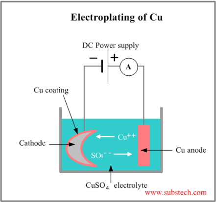
2 Electroplating
The most common application of the chemical effect of electric current is electroplating.
In this process, there exists a liquid, usually called the electrolyte, through which current passes. Two electrodes, connected to the terminals of a battery with a switch in between, are inserted in the liquid.
Electroplating is done in industries to have an anti-reactive coating on the parts of machines so that they do not react with the raw material, to have an anti-corrosive coating for the machines so that they do not get corroded, and a heat-resistive coating for parts like boilers to resist the heat produced by the machinery. Gold plating is one of the most common applications of electroplating in ornament-making.

Magnetic Effects

If a magnetic compass is placed near a conductor carrying current (wire), the needle is deflected. This shows that a conductor carrying current has a magnetic field around it.
The magnetic field around a current carrying straight conductor is in concentric circles. It can be observed by passing a current carrying straight conductor through a cardboard and sprinkling iron filings on it. All motors, transformers, Alternators and most of the measuring electrical instruments use magnetic effect of electric current.

Electro-Plating Effect Example
Electro-Plating Effect Example.

TIME CONSTANT FOR R-L CIRCUIT - THEORY PLUS QUESTIONS

Consider the Resistance-Inductance circuit shown few lines below, In the circuit on previous slide, if the coil was not present, the current through the resistor (may be a lamp) would immediately rise to its maximum value of E/R when you closed the switch. With the coil in the circuit, as soon as current starts to flow, the self-induction in the coil produces an emf across the coil, which, by Lenz’s Law opposes the change in current through circuit, thus, the rise of current in the circuit is not as fast as that was in pure resistive circuit containing no inductive element (coil).

The lamp thus experiences the sum of two opposing emfs, a constant one from the power supply, and an opposite, time-dependent one equal to -L di/dt from the self induction of the coil.
Over time, the current increases more slowly as it settles down to final steady state value, which causes the emf from self-induction in the coil to decrease, and finally after some time the current in the circuit approaches to E/R.


To find an expression for the current in the circuit, we note that the sum of the voltages across the resistor and the inductor equal the voltage applied by the power supply, or:
rl ckt
The solution to this differential equation is:
which we can also write as:
where τL, the inductive time constant, equals L/R.

L/R Time Constant

The time constant of a series RL circuit equal to the value of inductance divided by the resistance:

T = L / R

where,
T = time constant in seconds
L = inductance in henries
R = resistance in ohms

The LR TIME CONSTANT is a valuable tool for determining the time required for current in an inductor to reach a specific value. As shown in the illustration on next slide, one L/R time constant is the time required for the current in an inductor to increase to 63.2 percent of the maximum current. Inductor current build-up is considered complete at the end of 5 time constants. 
rl circiut

RL Decay Curve

Inductor current does not drop off at a steady rate. Rather, the rate of current decay is discharge is rapid at first, but slows considerably as the charge approaches zero.
During each time constant, the current decays 63.2% of the remaining distance to the minimum current level.
Inductor current decay is considered complete at the end of 5 time constants.
Questions for practice.

Q.1- What is the time constant of a series RL circuit where R = 1 kW and L = 1 mH?


Q.2- The steady-state maximum current through a 1.2 H inductor is 12 A. When this inductor is switched from the power source to a 1 W resistor, what is the current at the end of 3 time constants?