Consider the Resistance-Inductance circuit shown few lines below, In the circuit on previous slide, if the coil was not present, the current through the resistor (may be a lamp) would immediately rise to its maximum value of E/R when you closed the switch. With the coil in the circuit, as soon as current starts to flow, the self-induction in the coil produces an emf across the coil, which, by Lenz’s Law opposes the change in current through circuit, thus, the rise of current in the circuit is not as fast as that was in pure resistive circuit containing no inductive element (coil).
The lamp thus experiences the sum of two opposing emfs, a constant one from the power supply, and an opposite, time-dependent one equal to -L di/dt from the self induction of the coil.
Over time, the current increases more slowly as it settles down to final steady state value, which causes the emf from self-induction in the coil to decrease, and finally after some time the current in the circuit approaches to E/R.
To find an expression for the current in the circuit, we note that the sum of the voltages across the resistor and the inductor equal the voltage applied by the power supply, or:
The solution to this differential equation is:
which we can also write as:
where τL, the inductive time constant, equals L/R.
L/R Time Constant
The time constant of a series RL circuit equal to the value of inductance divided by the resistance:
T = L / R
where,
T = time constant in seconds
L = inductance in henries
R = resistance in ohms
L = inductance in henries
R = resistance in ohms
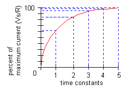
The LR TIME CONSTANT is a valuable tool for determining the time required for current in an inductor to reach a specific value. As shown in the illustration on next slide, one L/R time constant is the time required for the current in an inductor to increase to 63.2 percent of the maximum current. Inductor current build-up is considered complete at the end of 5 time constants.
RL Decay Curve
Inductor current does not drop off at a steady rate. Rather, the rate of current decay is discharge is rapid at first, but slows considerably as the charge approaches zero.
During each time constant, the current decays 63.2% of the remaining distance to the minimum current level.
Inductor current decay is considered complete at the end of 5 time constants.
Questions for practice.


"Great explanation of the time constant in R-L circuits! It’s such a crucial concept in electronics. For those diving deeper into electrical theory and related tech topics, I highly recommend visiting NGUYEN KIM THANH PHONG. It’s packed with resources and insights on electrical circuits, innovations, and much more. Keep sharing these awesome articles—looking forward to more!"
ReplyDelete