Wednesday, 1 February 2017

ENERGY POWER SUPPLY TECHNOLOGY - THE E.HOUSE TECHNOLOGY FOR DISTRIBUTION SYSTEM,

ehouse for power supply
Energy house for Power Supply - http://howelectrical.blogspot.com
Make the process of power distribution more efficient, reliable and safe with energy house power supply as new technology in Electrical power engineering and field. In many cities, infrastructures, buildings automation and industrial plants. They can be linked to industrial and building automation, and are rounded out by comprehensive support throughout the entire life-cycle. What are the benefits of Energy house for power supply solution? there are three main benefits as given below.


Benefits

There are three main benefits of energy houses for power supply solution.

  1. Cost Effective
  2. Fast to install
  3. Flexible

Cost Effective

The installation of an Energy house spare you from dealing with planning, controlling and complex civil works, as well as with crafts on site and construction risks.

Fast to Install

An energy house for power supply arrives at your site ready for plug commission and play. this really speeds up your lead time.

Flexible

You can choose from several energy house types according to your application requirements, equip them with exactly the products you need.

Plug and Play Power Distribution

The Energy house can also be used for plant balancing of fossil and renewable energy, as reliable power supply for critical processes, for grid coupling, as well as for the grid connection of electrical energy storage systems. Energy house are optimal approach to install electrical power and control equipment for a fast and reliable power supply. An energy house is a pre-fabricated electrical building, fully equipped. Actually industries needs a reliable and efficient power supply as well as flexible solutions that can be adapted to individual requirements. Energy house for power supply are fast and very easy way to install, can be used as an interim solution. They are easy to upgrade, and used available space optimally. This makes them the most suitable option for a broad range of application.
    The Energy house offer more; one stop solution, consistency, safety, flexibility, cost effciency, reliability and advanced technology.

Monday, 30 January 2017

TERTIARY WINDING OF TRANSFORMER - THREE PHASE TRANSFORMER

Electrical Transformer is a static device which transform electrical energy from one electrical circuit to another electrical circuit without any direct connection. It is also used for electrical power transmission (Step-Up) and distribution the electrical power (Step-Down) and Special purposes. Commonly we know that there are two windings in transformer, The primary winding and the secondary winding. The primary winding is used for input (not fixed) and the secondary winding is used for the output whether it depend upon the situation and requirement. Now there is a question asked an engineer from our Facebook group (Facebook-Group) that what is Tertiary winding in the three phase transformer, the advantages and disadvantages of tertiary winding.

Working Principle Of Transformer

The working principle of transformer is totally depends upon the Faraday's Law of mutual induction.
Faraday's Law of Mutual Induction is:
"Rate of change of flux linkage with respect to time is directly proportional to the induced EMF in a conductor or a coil."
As you all know well about the transformer working, I will try not to discuss here again. but the main constructional parts of the transformer I share below.

Main Constructional Parts of Transformer

There are following main part of transformer in construction.

  • Primary Winding
  • Secondary Winding
  • Magnetic Core of transformer
Now What is Primary winding? The Primary winding of transformer which produce magnetic flux when it is connected to electrical source. And What is the secondary winding? The Secondary winding of transformer is the flux, produce by primary winding, passes through the core will link with the secondary winding. This is also wound on the core of transformer and gives the desired output of the transformer. And the magnetic core of transformer is the magnetic flux produced by the primary winding that will pass through with low reluctance path linked with secondary winding and create a close magnetic circuit in the transformer.


tertiary winding how electrical blog


Tertiary Winding of Three Phase Transformer

As we already discuss, there are two windings in the transformer. There is another additional winding we used named "Tertiary Winding". This winding is used in the high rating transformer for the purposes below mentioned.  Because of this third winding, the transformer with tertiary winding is also known as three winding transformer.
Advantages of Tertiary Winding in three phase transformer
There are following advantages of tertiary phase winding.


  1. Tertiary Winding reduces the unbalancing in the primary due to unbalancing in three phase load.
  2. Tertiary Winding redistributes the flow of fault current.
  3. Sometime Tertiary Winding is required to supply an auxiliary load in different voltage level in addition to its main secondary load. This secondary load can be taken from tertiary winding of three winding transformer.
  4. As the tertiary winding is connected in delta formation in 3 winding transformer, it assists in limitation of fault current in the event of a short circuit from line to neutral.

Rating of Tertiary Winding.


Rating of tertiary winding depends upon its use. If it has to supply additional load, its winding cross - section and design philosophy is decided as per load, and three phase dead short circuit on its terminal with power flow from both sides of HV & MV. In case it is to be provided for stabilizing purpose only, its cross - section and design has to be decided from thermal and mechanical consideration for the short duration fault currents during various fault conditions single line to ground fault being the most onerous.

Saturday, 28 January 2017

WHAT IS TRANSDUCER, ITS TYPES AND WHAT IS THE APPLICATIONS OF TRANSDUCER

transducer


What Transducer Is?

A transducer is an electronic device that converts energy from one form to another. Common examples include microphones, loudspeakers, thermometers, position and pressure sensors, and antenna. Although not generally thought of as transducers, photocells, LEDs (light-emitting diodes), and even common light bulbs are transducers. A transducer plays a very important role in any instrumentation system.

Types Of Transducer:

There are many types of the transducer. Transducer can be classified into main types as below,
  • Quantity to be measured
  • Principle of Operation

Transducer as Quantity to be measured

  • Temperature transducer
  • Pressure transducer
  • Displacement transducer
  • Flow transducer

Transducer as Principle of Operations

  • Chemical transducer
  • Photovoltaic transducer
  • Photoconductor transducer
  • Half effect transducer
  • Piezoelectric transducer

Ideal Characteristics of Transducer

  • High dynamic range
  • High repeatability
  • Low Noise
  • Low hysteresis

Friday, 27 January 2017

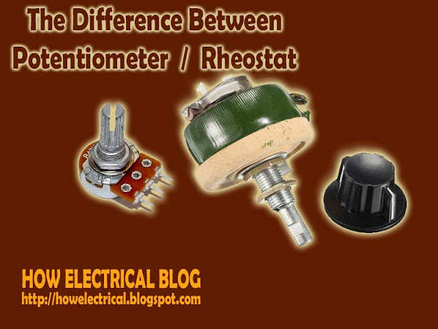
RHOESTAT AND POTENTIOMETER - THE DIFFERENCE BETWEEN RHEOSTAT AND POTENTIOMETER

potentiometer and rheostat


As looking wise, The potentiometer and the rheostat are looking same but there is some difference between both. I have shared some knowledgeable summarised difference below for understanding. If you found any more difference, You can share with us on below comment box.

POTENTIOMETER

A potentiometer is a three terminal variable resistor, Usually, electricians used the potentiometer to adjust voltage, The Potentiometer can work as Rheostat but The Rheostat can not works as Potentiometer because of their properties. The Potentiometer controls the circuit's Signal level (not the power level).

RHEOSTAT

A Rheostat is two terminal variable resistor, Usually, electricians use the rheostat to adjust current.  The Rheostat can not work as Potentiometer (but vice versa). Electricians employ a Rheostat for handling the much higher voltage and current. A Rheostat is simply a variable resistor used to control the power to a load.

A Rheostat is used to vary the amount of current in the circuit but a potentiometer is used to vary the voltage between the second terminal and one of the outside terminal.

Wednesday, 25 January 2017

UNDERSTAND THE HAZARDS OF ELECTRIC SHOCK ON BODY AND RULES FOR SAFE PRACTICE TO AVOID ELECTRIC SHOCK

Performance objectives

Understand the hazards of electric shock on human body and rules for safe practice to avoid electric shock. See how an amount of current is changed within the human body with the variation of resistance.

EQUIPMENT:                        

  • DC Ammeter
  • Multimeter with resistance  Range 9-12 Battery

What is Electric Shock

An electric shock occurs when a person comes into contact with an electrical energy source. Electrical energy flows through a portion of the body causing a shock. When Voltage increases current also increases. In most cases voltage up to 50 Volts is safe. Chart of Different Physiological effects of electricity

Safety Rules

The apparent reasons for accidents are
  1. Ignorance
  2. Fatigue
  3. Mental Pressure
  4. Faulty or Improper Tools 
  5. Wrong procedure and carelessness
  6. Rules for safe practice to avoid electric shock
  7. Be sure of conditions of the equipment's and dangers present before working on pieces of equipment. 
  8. Never Rely on safety devices.
  9. Never Remove the ground wire of three wire-input plugs.
  10. Do not work on cultured bench
  11. Do not work on wet floors
  12. Do not work alone
  13. Work with one hand behind you or in your pocket
  14. Never talk to anyone while working

MCB, MCCB, ACB AND VCB DIFFERENCE AND CHARACTERISTICS - CIRCUIT BREAKERS

Circuit Breakers of differents poles.


MCB (Miniature circuit breaker)

  • The characteristics of miniature circuit breaker are below,
  • MCB rated current is not more than 100 A. means the current limit (or current rating) is maximum 100A).
  • Trip characteristics are normally meant not adjustable.
  •  MCB operation is thermal based or thermal-magnetic.

MCCB (Moulded case circuit breaker)

  • The characteristics of Moulded case circuit breaker are below,
  • The current rating of MCCB is from 101 A to 1000 A.
  •  The Current of a trip (switch off the circuit) may be adjustable, means current rating we can adjust in MCCB.
  • MCCB operates in thermal or thermal-magnetic operation.

ACB (AIR Circuit Breaker)

  • The characteristics of ACB (Air Circuit Breaker) are below.
  • The current rating of ACB (Air circuit breaker) is from 1001 A to 10000 A.
  • Trip characteristics of Air Circuit Breaker (ACB) often fully adjustable including configurable trip thresholds and delays.
  • ACB (Air Circuit Breaker) often used in Main Electrical Panels (usually in medium voltage MV or high voltage electrical panels HV). ACB (Air circuit breaker) also usually used for main power distribution in a large industrial plant, where the breakers are arranged in drawn-out enclosures for ease of maintenance.

VCB (Vacuum Circuit Breaker)

  • Some important characteristics of Vacuum circuit breaker are below,
  • The VCB (Vacuum circuit breaker) current rating is up to 3000 Amperes.
  • The main characteristics of vacuum circuit breaker are, it interrupts the arc in a vacuum bottle.
  • These can be applied at up to 35 thousand volts.
Is there any other you know, Share with us from below comment box.

Monday, 23 January 2017

WHAT IS DIELECTRIC - ELECTRICAL TECHNOLOGY BLOG - HOW ELECTRICAL WORKS.

A dielectric is an electrical insulator that can be polarized by an applied electric field.
When a dielectric is placed in an electric field, electric charges do not flow through the material as they do in a conductor, but only slightly shift from their average equilibrium positions causing dielectric polarization.

 Because of dielectric polarization, positive charges are displaced toward the field and negative charges shift in the opposite direction. This creates an internal electric field which reduces the overall field within the dielectric itself.

While the term "insulator" implies low electrical conduction, "dielectric" is typically used to describe materials with a high polarizability. The latter is expressed by a number called the dielectric constant.

The term insulator is generally used to indicate electrical obstruction while the term dielectric is used to indicate the energy storing capacity of the material (by means of polarization).
If the space between the plates of a capacitor is filled with an Dielectric, the capacitance of the capacitor will change compared to the situation in which there is vacuum between the plates.

The change in the capacitance is caused by a change in the electric field between the plates. The electric field between the capacitor plates will induce dipole moments in the material between the plates. These induced dipole moments will reduce the electric field in the region between the plates. A material in which the induced dipole moment is linearly proportional to the applied electric field is called a linear dielectric.

For linear dielectric:

Where K is called the dielectric constant. Since the final electric field E can never exceed the free electric field Efree, the dielectric constant k must be larger than 1.
The potential difference across a capacitor is proportional to the electric field between the plates.

Since the presence of a dielectric reduces the strength of the electric field, it will also reduce the potential difference between the capacitor plates (if the total charge on the plates is kept constant):

The capacitance C of a system with a dielectric is inversely proportional to the potential difference between the plates, and is related to the capacitance Cfree of a capacitor with no dielectric in the following manner.


Since k is larger than 1, the capacitance of a capacitor can be significantly increased by filling the space between the capacitor plates with a dielectric with a large k.
The electric field between the two capacitor plates is the vector sum of the fields generated by the charges on the capacitor and the field generated by the surface charges on the surface of the dielectric.

INDUSTRIAL WIRING COURSE - ELECTRICAL WIRING - LEARN ELECTRICAL DRAWING

how electrical drawing


Electrical Wiring or Industrial Wiring course files in which you can learn these following topics in the field of Electrical Engineering.

TOPICS YOU WILL LEARN

  1. Safety of Industry/industrial wiring safety/industry safety
  2. Drawings and symbols of electrical wiring.
  3. Wire types and preparations (include insulation materials, conductors, wire specification, coxial and multiway cables and insulation  removal process.)
  4. Soldering and termination (how to solder a wire connections, forming the wire, crimped joints, screw clamp terminals and termination coaxial cable.)
  5. Cable forming connections and routing (general intro about connections and routing, conductor and cable runs and conductors of different circuits.)
  6. Hardware (components mounting rails usually known as aluminuim rails, plastics trunking or usually known as cable channel made of plastic materisl, connector blocks and screw terminals).
  7. Active components like connectors and relays, contactors and transformers etc.
  8. Passive components like fuses, resistors and capacitors.
  9. Switched and lamps.
  10. Earthings and screenings (earthing the protective bonding circuit, screen connections and more)
  11. The most important and advaced thing is PLC Wiring. (In which you will learn about
  12. PLC installation, Power supply wiring, earthing and wiring of inputs and outputs.
Want to learn these all? Download these files with complete Wiring course from below link.